It can be bought of almost any width in large or small rolls and is sold by the yard or pound.
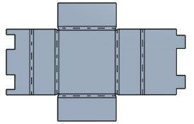
Sheet metal flat pattern drafting.
See document 10 0005 blah drawing drafting standards and practices for the proper setup of a sheet metal drawing.
The select face in the upward face tab highlighted in the flat pattern dialog box click ok to finish the flat pattern command.
This is a common occurrence when manufacturers receive a sheet metal layout dimensioned in the flat pattern.
Start the drafting application.
Sheet metal layout tip.
As the default view is to have all features included it would mean that when you add a sheet metal part to an assembly it will be the flat pattern.
The descriptions are clear and well organized step by step.
In the sheet metal view area select flat pattern view.
The paper generally used for sheet metal pattern drafting is known as brown detail paper.
In a sheet metal part create a new configuration.
In the sheet metal application select the face on the sheet metal model to specify a reference face for flattening.
Set other options in the drawing view dialog and then click in the drawing to place the view.
Click place views tab create panel base.
No matter the situation it s difficult to watch your hard work go to waste.
Select process bends and all of the features after it.
The paper should be of medium thickness very strong and tough because.
And if you wish to create a 2d wireframe flat pattern suitable for drafting or use in creating the manufacturing data needed to create the unformed blank then use the.
However for finished drawings white craft paper is more suitable.
Right click flat pattern and select unsuppress.
Click edit suppress this configuration to suppress all of the selected features.
If appropriate select or clear the selection of the recover punch center option.
Requirements for sheet metal part drawings sheet metal parts are typically created from material less than 250 inches thick and are formed by folding the material at specific locations with a controlled bend radius.
Also each problem presented is drawn to scale or dimension given and is of ample size for constructing from metal using a minimum amount of material.
Activate the sheet metal application.
Click place views tab create panel base.
If appropriate select or clear the selection of the recover punch center option.
The proper sequence so necessary for successful instruction in sheet metal pattern drafting is an important feature of this book.
In the featuremanager design tree do one of the following.
In the drawing view dialog box select a sheet metal component as file.
It seems like this method is similar to creating simplified reps and will cause a problem when assembling a sheet metal part.
Dimension to formed view not flat pattern.

